AVR Tutorial - Getting Started: Blinking an LED
Blinking an LED is the "Hello World" of programming microcontrollers. It is a great way to work through the entire development process and make sure all your tools are in working order.
Wiring The Circuit
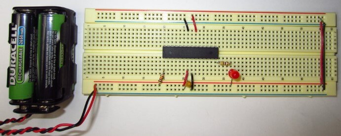
The schematic diagram for the Blink LED project is shown in first figure. A photo of the circuit wired up on a breadboard is shown in second figure.
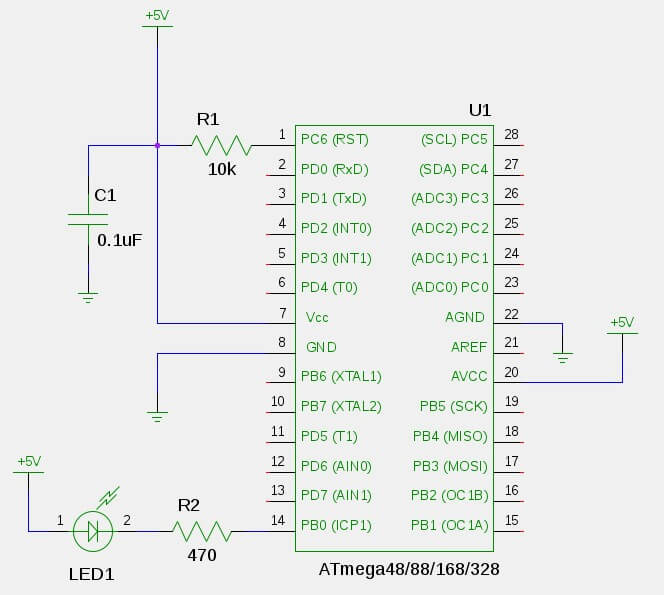
If you are not familiar with wiring integrated circuits (ICs), the AVR chip have a little notch at one end to designate the "top". The pin numbering starts at 1 on the top left, progress squentially down the left side, and then back up the right side as shown in the schematic above.
A 10kΩ "pull-up resister" (R1) is connected to the RESET pin to keep the pin in a digital high state.
A 470Ω resistor (R2) and an LED (LED1) are connected to pin PB0. The resistor is a "current limiting" resistor to limit the current (mA) passing through the LED so that it doesn't burn out. When PB0goes low (0V) the LED will turn on. When PB0 goes high (+5V) the LED turns off.
A 0.1uF "bypass capacitor" (C1) helps prevent noise or "ripple" on the +5V line from effecting the microcontroller.

Powering The Circuit
The schematic shows a DC power source of +5V to power the microcontroller, however, it's up to you to provide that +5V. One of the most common ways hobbyists use provide +5V to projects is to use a 9V battery with a 7805 voltage regulator IC to drop the voltage down to +5V.
I prefer to use 4 rechargable AA batteries (4 batteries x 1.2V ea. = 4.8V). You can pick up rechargable AA batteries and chargers just about anywhere these days. You can wire them up to you breadboard using a 9V Battery Clip as shown in figure 2.3.
Of course, having a +5V power source in your "lab" (whatever that may be) is invaluable. Hobbyists often get +5V out of a wall outlet by using an expensive lab power supply (which is awesome if you can afford it), using a +5V AC/DC wall adaptor, using the +5V line of an ATX computer power supply, or tapping the +5V line from a USB bus or USB charger.
Compiling the C Program
The C program must be compiled into an Intel HEX formated file. This is the format that is passed to avrdude which tells the AVR programmer what to program into the microcontroller. The HEX file is created in two steps.
First, avr-gcc will be used to compile the C program blink.c into a binary ELF (Executable andLinkable Format) object file. This new file will be named blink.elf.
avr-gcc -mmcu=atmega328p -Wall -Os -o blink.elf blink.c
-mmcu, tells the compiler which AVR microcontroller the code is being compiled for. If you are not using anATmega328Pthen you will need to change it to the AVR that you are using.-Wallturns on all reasonable compiler warnings which will help make sure you're writing good code. Any time you see a warning you will want to investigate what it means.-Osis the optimization flag which tells the compiler to optimize the code for efficient space utilization.-oargument specifiesblink.elfas the output filename.
Next, avr-objcopy copies specific sections of binary data from the blink.elf file into a new Intel HEX format file. The new file will be named blink.hex.
avr-objcopy -j .text -j .data -O ihex blink.elf blink.hex
-jspecifies Memory Sections to copy from the ELF file. It is used twice, once to copy the.textsection and once for the.datasections. The.textsection contains the machine instructions which make up the program. The.datasection contains various static data used in the program.-O ihexoption specifies Intel HEX as the output format.blink.elfis passed as the input file andblink.hexis specified as the output file.
The Blink LED program doesn't actually use the .data section, but most projects will. Including it now won't hurt anything.
The blink.hex file is now ready to be programmed into the AVR.
The Blink LED Program
As was described in Overview of the Development Process, the "firmware" which tells the AVR microcontroller what to do is written in C. The GNU Toolchain is used to compile that code into a file formatted for programming into the AVR.
The C program for Blink LED is shown below.
#define F_CPU 1000000UL

#include <avr/io.h>
#include <util/delay.h>

int
main (void)
{
    DDRB |= _BV(DDB0);

    while(1)
    {
        PORTB ^= _BV(PB0);
        _delay_ms(500);
    }
}
This code configures the PB0 pin on the AVR microcontroller as a digital output. Then, it toggles the state of that pin every 500 ms. For now, just copy and paste this code into a file named blink.c.
Programming the AVR Microcontroller
Now for the moment of truth. The blink.hex file will now be programmed into the microcontroller using the avrdude program. Make sure the AVR programmer is connected to your circuit and to your computer and that the circuit has power. Then you can run the avrdude command:
avrdude -p m328p -c usbtiny -e -U flash:w:blink.hex
-pspecifies the AVR microcontroller part number being programmed. If you are not using anATmega328Pthen you will need to specify the AVR you are using.-cspecifies the AVR programmer you are using. If you are not using a USBtinyISP then you will need to specify the AVR programmer you are using.-eerases the chip before writing the new contents-U flash:w:blink.hexperforms a memory operation:flashis the type of memory,wis for a "write" operation, andblink.hexis the name of the file to write. In other words, "write blink.hex to flash memory".
If the AVR microcontroller was successfully programmed then the LED should start blinking about once per second and the output of avrdude should look like the following:
avrdude: AVR device initialized and ready to accept instructions

Reading | ################################################## | 100% 0.01s

avrdude: Device signature = 0x1e950f
avrdude: erasing chip
avrdude: reading input file "blink.hex"
avrdude: input file blink.hex auto detected as Intel Hex
avrdude: writing flash (200 bytes):

Writing | ################################################## | 100% 0.61s

avrdude: 200 bytes of flash written
avrdude: verifying flash memory against blink.hex:
avrdude: load data flash data from input file blink.hex:
avrdude: input file blink.hex auto detected as Intel Hex
avrdude: input file blink.hex contains 200 bytes
avrdude: reading on-chip flash data:

Reading | ################################################## | 100% 0.38s

avrdude: verifying ...
avrdude: 200 bytes of flash verified

avrdude: safemode: Fuses OK

avrdude done.  Thank you.
Congratulations, you have now programmed an AVR microcontroller!
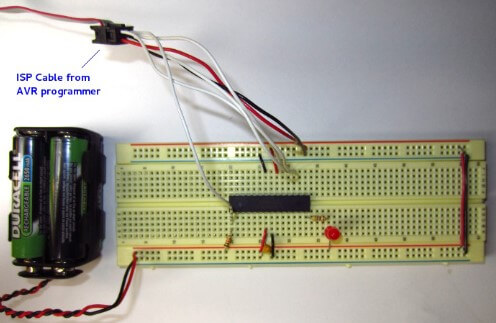
Connecting the AVR Programmer
The AVR microcontroller will be programmed, in it's circuit, right where it is on the breadboard. This is known as In System Programming or ISP. Connecting the AVR Programmer's ISP cable to the microcontroller on the breadboard can be a little confusing at first, so bear with me.
There are 2 standard ISP connections. A 10-pin and a 6-pin connection. The AVR Programmer typically has a 6 or 10 pin ribbon cable comming out of it. This cable is meant to be connected to what's known as a "shrouded header" on a PCB (printed circuit board). The ISP cable does not directly plug directly into a breadboard without some help.
The cheap and simple way to connect the ISP cable to the breadboard is to simply stick hookup wire into the ISP cable connector and then to the corresponding pins on the AVR microcontroller.

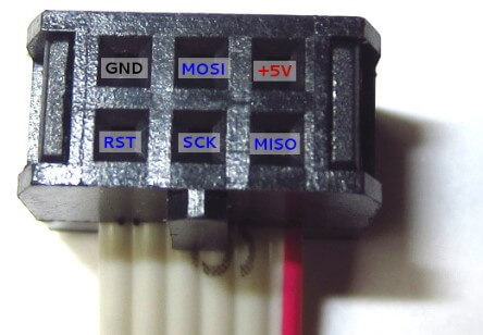
In order to connect the ISP cable, a pinout diagram is used to determine which pins of the ISP connection correspond to which pins on the AVR microcontroller. The pinouts for the 6 and 10 pin ISP connectors are shown below. The square pin in the pinout depicts pin 1. The red conductor on a ribbon cable also depicts pin 1.

The trick to this is that the pinout is for the header, not the cable. In other words, it depicts the pins of the header that the cable would plug into, as would be seen from above. If you are looking into the plug-end of the cable, you are looking at it flipped over (as if from underneath the PCB). It's easy to inverse the connections if you do not understand the pinout diagram.
Connect hookup wire from the ISP cable to the corresponding pins of the AVR microcontroller on the breadboard.
Troubleshooting
If the AVR programmer's ISP cable is not properly connected to the AVR microcontroller or the circuit does not have power, avrdude will show an error like this:
avrdude: initialization failed, rc=-1
         Double check connections and try again, or use -F to override
         this check.