AVR Tutorial: Introduction and Digital Output
The AVR family of 8-bit microcontrollers from Atmel are quickly growing in popularity for electronics and robotics hobbiests. Their major selling point for me, as opposed to the PIC microcontrollers from Microchip, are their being designed to be developed using higher languages such as C. This allows them to be developed using the open-source GNU tools (gcc). This works out especially well for me working in Linux. This tutorial series is for working with avr-libc, the C library for AVRs using the GNU tools. This first tutorial will simply get you familiar with a basic C program for an AVR. Like so many other introductory tutorials, we'll simply be turning an LED connected to the microcontroller on and off.
Circuit
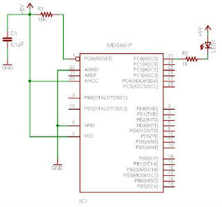
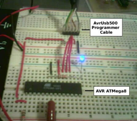
The circuit is very simple. PC0 is being used as a digital output pin. We connect an LED through a 1k resistor to PC0 and VCC. We can connect the LED directly to the IO pin beacuase ohms law tells us that with VCC at 5V, when the PC0 pin is low, we'll be sinking 5mA of current, which is well within range of the IO pin maximum curent rating. The RESET pin is an "active-low" reset, which means that it resets the MPU when it is digital low (tied to ground). Therefore, we hardwire the RESET pin to VCC through a resistor to limit current. The 0.1uF capacitor should be mounted (or inserted in your breadboard) very close to the VCC pin to filter noise on the line and prevent the chip from resetting or behaving eratically. It's common practice to place a capacitor like this on each VCC input of ICs in a digital system. It is assumed that you are using an ATMega8 as it comes from the factory. In this condition, the chip is programmed to use it's own internal oscillator at 1MHz. Therefore, there is not a crystal oscillator or other external clock source in this circuit-- it's not needed!


Source Code
The source code for this simple project is contained in main.c. We're going to step through this really slowly for this first tutorial.
#define F_CPU 1000000UL /* 1 MHz Internal Oscillator */
#include <avr/io.h>
#include <util/delay.h>
F_CPU defines the clock frequency in Hertz and is common in programs using the avr-libc library. In this case it is used by the delay routines to determine how to calculate time delays. Often, this call will be surrounded by #ifndef and #endif so that it can alternately be defined in the Makefile (more on that later). The first include file <avr/io.h> is part of avr-libc and will be used in pretty much any AVR project you work on. io.h will determine the CPU you're using (which is why you specify the part when compiling) and in turn include the appropriate IO definition header for the chip we're using. In this case, we'll be using the ATMega8 and so, the iom8.h file will be included. This file is located in avr/include/avr relative to where you installed avr-libc. In my case, it's at /usr/local/avr/avr/include/avr/iom8.h. If you look at this file, you'll see it simply defines the constants for all your pins, ports, special registers, etc. For the most part, the label that is used to define a port, pin, or register in the datasheet is what is defined by this header. So if the datasheet says PORTC, we now have PORTC defined for us. The <util/delay.h> library contains some routines for short delays and requires the F_CPU definition as discussed above. The function we'll be using, is _delay_ms(). The delay.h file ALSO includes <inttypes.h>, which according to the avr-libc reference, "includes the exact-width integer definitions from <stdint.h>, and extends them with additional facilities". We'll be using these types throughout our code.
/* function for long delay */
void delay_ms(uint16_t ms) {
 while ( ms )
 {
 _delay_ms(1);
 ms--;
 }
}
This function, delay_ms(), uses the _delay_ms() function as mentioned above. Theavr-libc reference for _delay_ms() states: "The maximal possible delay is 262.14 ms / F_CPU in MHz". Since we're using the internal 1MHz oscillator, we're going to end up with a maximum delay of 262 mS using this function. However, I want a delay of 1 whole second for my LED toggling program. So, in this function we will call the _delay_ms() function for 1 mS in a loop. The function's ms parameter is of type uint16_t which is an exact 16-bit data type. This function does add a few instructions making the delay not exact mS delays, however, it's close enough for many purposes. For exact timing, timers should be used which is beyond the scope of this tutorial.
int main (void)
{
 /* PC0 is digital output */
 DDRC = _BV (PC0);
 /* loop forever */
 while (1)
 {
 /* clear PC0 on PORTC (digital high) and delay for 1 Second */
 PORTC &= ~_BV(PC0);
 delay_ms(1000);
 /* set PC0 on PORTC (digital low) and delay for 1 Second */
 PORTC |= _BV(PC0);
 delay_ms(1000);
 }
}
Our main routine has two parts to it. First, we setup/initialize our AVR, and then we enter an infinate loop where our program runs. DDRC is the Data Direction Register for PORTC (see "I/O Ports" in the datasheet). This register determines whether the pin is a digital output or a digital input, where a 1 represents an output and a 0 represents an input. Initially, the DDRC register is all 0 (0x00 or 00000000b). The statement DDRC = _BV (PC0); sets the PC0 bit. _BV() is a compiler macro defined as #define _BV( bit ) ( 1<<(bit) ) in <avr/sfr_defs.h> which was included already indirectly through <avr/io.h>. It stands for Bit Value where you pass it a bit and it gives you the byte value with that bit set. PC0 was defined in iom8.h as 0. So the compiler will actually place DDRC = 0x01; in place of DDRC = _BV (PC0);. So now we've set PC0 as a digital output. If you are already familiar with bitwise operators in C and how to clear and set bits, you should skip ahead to Building the Project. In each iteration of the infinate loop (while (1)) we are using standard C methods for setting and clearing the PC0 bit followed by 1000 mS delay between each set and each clear. Let's take a closer look at each of those. The first, is to clear the bit using PORTC &= ~_BV(PC0); which turns off the LED (remember that the LED is connected to VCC, so a logical 1 output results in little to no voltage across the LED). Remember that our _BV macro returns the bit set in byte form, in this case, 0x01 or 00000001b. So, the statement PORTC &= ~_BV(PC0); is actually PORTC &= ~0x01;. The bitwise operator ~ will "not" the value first, which results in 11111110b. So now we basically have PORTC &= 0xFE;. With this, the bit in position 0, PC0, will ALWAYS be cleared after this statement without effecting the other bits in the byte. So regardless of the value currently in PORTC, only the bit we're clearing is changed. Take a look:
 10101010 0xAA
& 11111110 0xFE
 -------- ----
 10101010 0xAA Bit 0 is still clear, other bits uneffected.
 01010101 0x55
& 11111110 0xFE
 -------- ----
 01010100 0x54 Bit 0 is cleared, other bits uneffected.
Now, in this demonstration, bit 0 (PC0) is the ONLY bit we're working with, however, you can see how clearing a bit works. After delaying for 1 second, we then set the bit using PORTC |= _BV(PC0);. This works very similarily to the previous explanation of clearing a bit. The equivelent statement is PORTC |= 0x01; meaning we're "or-ing" PORTC with 00000001b.